By Mike Brengel, P.E., M.SAME, and Aaron Schaubach, P.E.
In planning the renovation for Dry Dock 4 at Norfolk Naval Shipyard, advanced 3D and scale modeling informed the design choices that would prepare the facility for another 50 years of service while meeting increased standards for resiliency and redundancy.
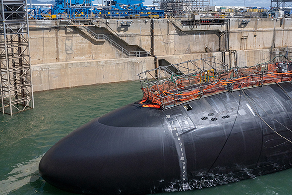
For more than 100 years, Dry Dock 4 at Norfolk Naval Shipyard, Va., has been part of the critical infrastructure required to maintain and repair naval surface vessels and submarines, keeping America’s feet protecting the freedom of the seas. Over the past half-century, the dry dock has been in nearly constant use to perform regularly scheduled maintenance, primarily on nuclear-powered submarines.
However, the constant stream of naval vessels resulted in a steady deterioration of the large volume pumps and related equipment, as well as the overall containment structure. This critical infrastructure reached a point where an entire overhaul was needed to prepare the dry dock for the next 50 years of heavy service. A joint venture design team of Mofatt & Nichol and Burns & McDonnell was brought onboard to help facilitate this unusually complex project.
In recognition of the need to overhaul and renovate dry dock facilities at each of its four main repair and maintenance shipyards, the U.S. Navy, in 2018, launched a multibillion-dollar Shipyard Infrastructure Optimization Program (SIOP). With a ribbon cutting in April 2023, Dry Dock 4 became the first SIOP project to be completed, and, as a result, could be considered a pilot demonstration of the engineering design and testing protocols needed to fully comply with the rigorous standards set by the Hydraulic Institute for pump well design.
The overall series of design options tested with the scale model allowed the team to validate and measure performance of all enhanced design features. Additionally, it allowed them to test how they would perform under real-world conditions versus theoretically in a computer model.
A Needed Overhaul
Dry Dock 4 was initially constructed in 1917 and had been through a number of repairs over the decades since, but nothing within the last 45 years. When the recent overhaul project kicked of, the dry dock was essentially a heavily used, 100-year-old structure that had not been renovated since 1975.
The dry dock facilities at Norfolk Naval Shipyard are composed of large concrete structures sitting below the surface of the adjacent Elizabeth River. A caisson locking gate is positioned at one end of these structures to open and close, permitting vessels to enter or exit the dock area. Once a submarine is in position, the pumps situated within the pump well are activated to expel water from the chamber; this allows the vessel to slowly settle onto the keel blocks that will hold it in place for the duration of its maintenance cycle.
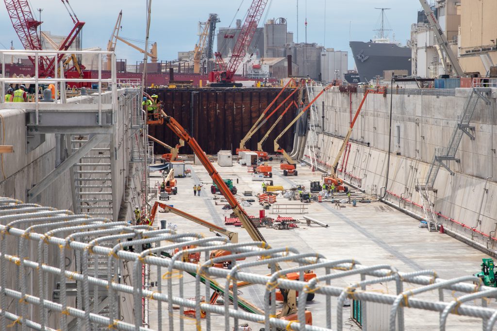
Deterioration of essential infrastructure within Dry Dock 4 meant that repairs and maintenance to pumps and other equipment were continually needed. Even with the heavy cycle of repairs, the facility was at risk of not meeting the shipyard’s long-term mission requirements. The internal pump well system, and some piping and other components, had reached their end-of-life service date.
To regain the Navy’s standard of performance efficiency, it was necessary for the pump well renovation to comply with Hydraulic Institute codes and standards (adherence to what the nonprofit organization sets has become the gold standard for operation, installation, performance, and testing of pumps, as well as the manufacturing of pumps and related components).
In essence, greater resilience and redundancy was essential. This meant the three existing 110,000-gal/min dewatering pumps would need to be replaced with three new compliant pumps. Additionally, the two 5,000-gal/min drainage pumps that were needed to remove water from the lower portions of the containment structure would also need to be replaced by three 5,000-gal/min pumps.
Leveraging Digital Tools
Overhauling a century-old structure that was designed well before any Hydraulic Institute standards were established meant that every detail of how water flowed in and out of the structure would need to be analyzed, since nothing in the system could inherently meet required criteria.
Following award of the design contract in 2018, the first step for the project team was to undertake a laser scan of the entire dry dock—from the basin to every chamber, as well as culverts and fumes. This was necessary to gain a precise picture of how water enters and exits these confined spaces.
The scan produced millions of data points to create a point cloud that then fed data to create a 3D-scale model representation of the actual physical structure. This highly accurate model had variances of only a millimeter or less. It would have been nearly impossible to create the model with similar accuracy if it had only been based on record engineering drawings alone. This essential first step allowed the team to compare digital files with decades of existing drawings for an extra step of verification.
Setting a Baseline. With the model developed, the next step included a computational fluid dynamics (CFD) modeling exercise to set baseline performance for velocity, and other desired characteristics, for the water exiting the chamber, within Hydraulic Institute standards.
Utilizing fluid mechanics, CFD applies algorithms and other data methods to develop a representational model that reflects principles of mass, momentum, and energy conservation. This model then was subjected to verification and further testing of conformance within the required standards by a third-party subconsultant. Ultimately, the work allowed the team to pinpoint a number of performance factors for water flow that needed to be corrected in the design.
Scale Model Tests
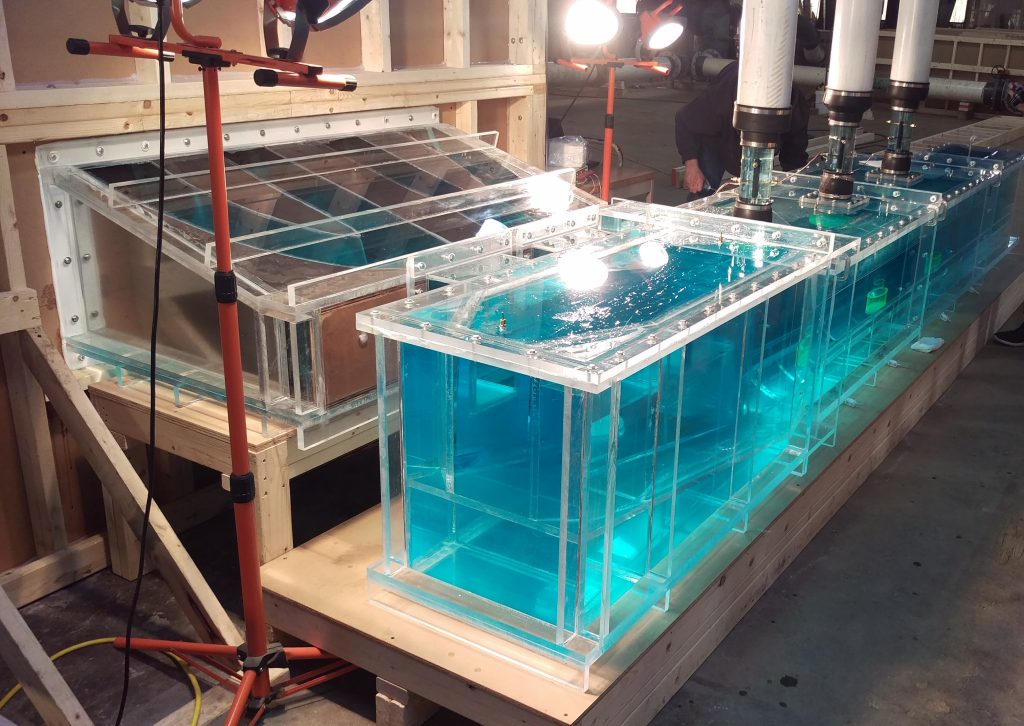
With accurate digital models supported by the CFD analysis, construction of an accurate physical model was commissioned that could be used for testing water flow characteristics. The model had to precisely represent every curvature and nuance of the actual physical structure, starting at the fumes and working to the suction chamber. This element of the project would have been impossible without the laser scans and 3D modeling.
Analyzing Conditions. The scale model was constructed out of polycarbonate panel material and custom fabricated for the complex geometry of all portions of the physical dry dock chamber. Once an accurate replica was made, the team was able to conduct testing of how water moved through the actual structure. This allowed them to explore exactly what was happening to cause conditions such as vortex formations.
With those careful observations and measurements made, a number of design variations were explored to address potential issues. This allowed the team to observe factors that may not always be fagged in a CFD analysis. For example, some transient conditions that lead to vortex formations may not show up accurately in the model (they can only be detected through direct observation). Recognizing the limitations of CFD analysis, with verification and testing via a physical scale model, was an important step to achieve compliance.
Navy personnel joined in this direct observation and testing exercise. the team was able to document degradation of performance within the existing dry dock structure and collaborate on targeted solutions to address those deficiencies. For example, a particular design iteration called for placing suction baskets on the inlets of pumps to limit vortexing inside pump columns. Gaining visibility of how vortexes were forming within the scale model provided insight into solutions that could be designed and tested at scale. Consequently, a grated structure was designed for placement in the ceiling portion of the column as a design element to help create more uniform flow.
The overall series of design options tested with the scale model allowed the team to validate and measure performance of all enhanced design features. Additionally, it allowed them to test how they would perform under real-world conditions versus theoretically in a computer model.
With validated design upgrades in hand, the next step was to create detailed engineering drawings at 1:1 scale for the dry dock. These included fabrication drawings for the new inlet baskets and the grated structure that was added to the ceiling to mitigate vortex formation.
Increasing Resiliency
Among the core objectives of SIOP is increased redundancy and resilience for all critical maintenance and repair facilities. Within Dry Dock 4, two discharge pumps had long been utilized, but the scope of the project required installing an additional pump in order to add a safety margin that was previously absent while maintenance was being performed.
A tight chamber presented challenges to configure enough space to add the additional pump. The two previous pumps were configured with drive shafts that extended from a motor situated above the waterline to a connection with the submersible pumps below. The long drive shaft required a number of flexible joints that articulated down to the pump. This setup resulted in continual maintenance issues due to mechanical loss and breakdowns related to stress on the joints. A total of four design options were explored, with the final solution being to install three submersible pumps with motors also situated below the waterline, directly coupled to the pumps within a watertight containment structure.
Taking Additional Steps. Another requirement for additional redundancy during the project was to add a second discharge outlet to the Elizabeth River. Because the Navy had an existing discharge permit allowing for a single discharge point, an environmental study was required to assess compliance with clean water standards for this additional discharge.
A mixing zone study performed for the Virginia Department of Environmental Quality resulted in the design of a multiport diffuser system that incorporated a series of nozzles to help mitigate any concerns over substances or temperatures that could adversely affect aquatic life living near the outfall.
The resilience mandate also included a recognition of potential sea-level rise, climate change, and future extreme weather events anticipated during the 50-year lifecycle of the new dry dock. This concern was addressed by raising coping walls that surrounded the facility by an additional 5-ft -providing enough protection to address levels of a 500-year flood.
Essential Infrastructure
The mission of the Dry Dock 4 renovation was to achieve a compliant modern system that reduces wear and tear on the pumps and maximizes performance efficiency. With these facilities utilized up to 90 percent of the time year-round, achieving this goal is critical. Not only does an Hydraulic Institute-compliant system reduce maintenance hassles, it also addresses most issues related to voided warranties for pumps and related systems.
The project required three years to complete, during which the facility was not available to support the feet’s maintenance operations. This was a significant commitment, and recognizes the importance of reliable maintenance executed through dry dock facilities to achieve the Navy’s broader mission for the nation.
Mike Brengel, P.E., M.SAME, is Project Manager at Burns & McDonnell
Aaron Schaubach, P.E., is Senior Mechanical Engineer, Burns & McDonnell
They can be reached at mjbrengel@burnsmcd. com; and atschaubach@burnsmcd.com.
The views presented are those of the authors and do not necessarily represent the views of the Department of Defense or its components.
More from TME
-

Delivering for Diverse Operational Needs at Hill AFB
A new U.S. Navy Reserve Center at Hill AFB required careful design and execution coordination to meet multifaceted mission needs, along with maintaining flexibility and innovation in its design to stay on schedule. -
Improving NAVFAC’s Facilities Construction Community
Naval Facilities Engineering Systems Command has implemented a series of process improvements across its construction workforce to increase recruitment, validate and standardize mastery of processes and procedures, and recognize accomplishments of personnel. -
Modernizing Dry Dock No. 1 at Naval Base San Diego
A recent project to modernize Dry Dock No. 1 at Naval Base San Diego will allow the facility to service modern vessel types while increasing its reliability for decades.